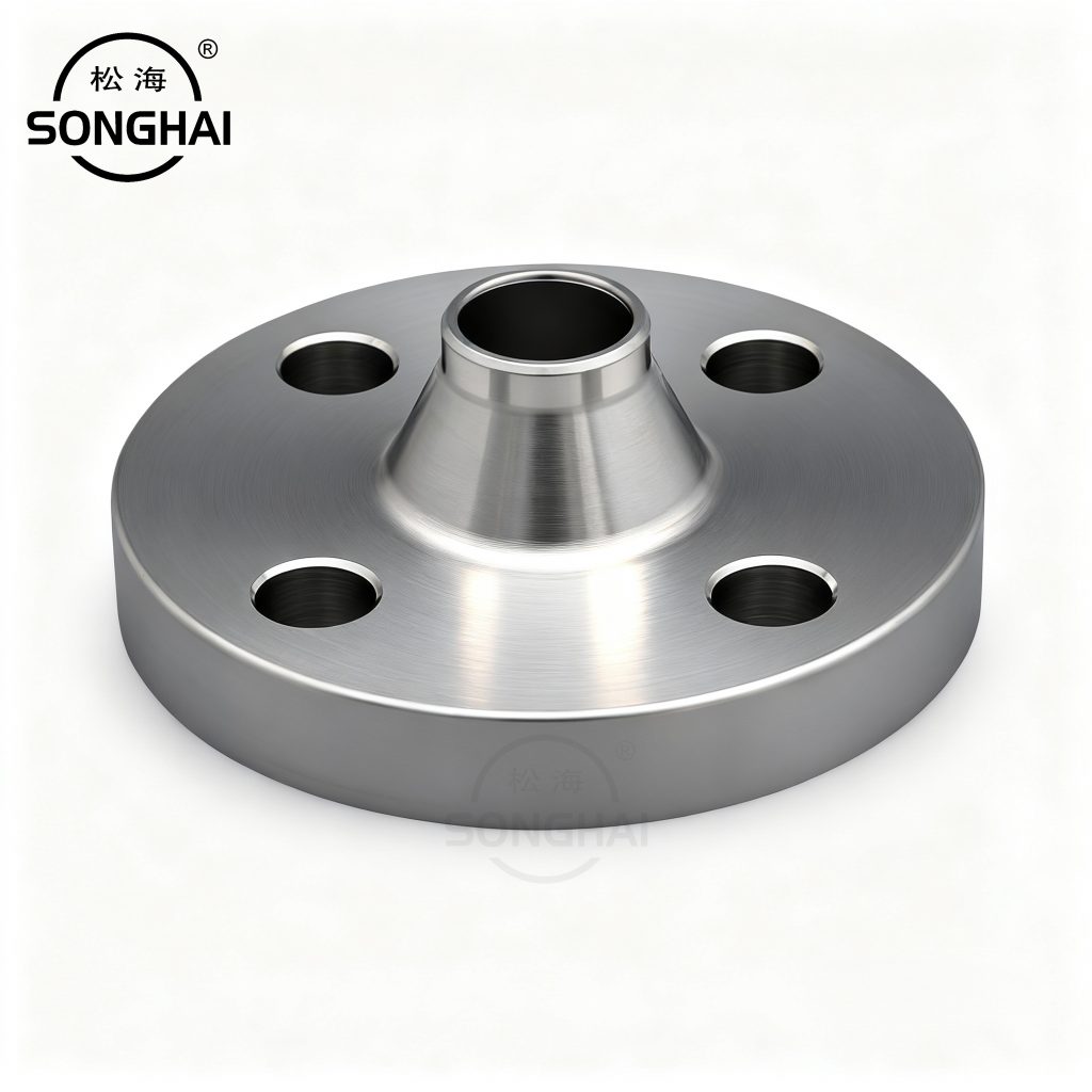
A lap joint flange and stub end assembly is designed for piping systems that must be dismantled without turning flange bolt-hole alignment into a maintenance problem. Unlike a one-piece weld neck or slip-on flange, the pressure-facing component and the backing ring have separate jobs. The stub end is welded to the pipe and provides the gasket seating face; the loose lap joint flange supplies the bolt circle and can rotate freely around the stub end.
This guide explains how a lap joint flange and stub end work together, where the design delivers value, and what procurement and installation teams should specify before ordering. It is intended as a practical engineering guide; the applicable piping code, project specification and approved drawings always govern the final design.
What is a lap joint flange and stub end?
A complete lap joint stub end connection normally includes a pipe stub end, a loose backing flange, a gasket, mating flange or equipment flange, and bolting. The stub end has a formed lap face at one end and a butt-weld end at the other. The backing flange is not welded to the pipe. It slides over the stub end and is free to rotate, making bolt holes easier to line up during fabrication and maintenance.
| Component | Primary function | What to verify |
|---|---|---|
| Stub end | Provides the process-wetted transition and gasket seating surface | Material, pipe schedule, lap geometry, weld preparation and facing |
| Lap joint flange | Provides the bolt circle and clamp load path | Standard, class/rating, bolt pattern, material and dimensional compatibility |
| Gasket | Creates the seal between compatible faces | Medium, temperature, pressure, facing and approved gasket type |
| Bolting | Develops and maintains controlled clamp load | Grade, coating/lubrication, tightening sequence and inspection requirements |
Why use a stub end flange assembly?
The principal advantage is maintainability. Because the backing ring can rotate, crews can align bolt holes without rotating a welded pipe spool or forcing piping into position with bolts. That benefit is valuable at exchangers, filters, valves, removable spools and equipment nozzles where periodic opening is expected.
A stub end and lap joint flange arrangement can also support an economical material strategy. For corrosion-resistant service, the stub end may be made from the alloy required in contact with the process fluid, while the loose backing flange is selected according to the surrounding environment and project specification. This is not an automatic cost reduction: compatibility, temperature, external loads and galvanic-corrosion risk still require engineering review.
Lap joint flange versus a weld neck flange
| Decision point | Lap joint flange with stub end | Weld neck flange |
|---|---|---|
| Connection form | Stub end is butt welded; backing flange remains loose | Flange neck is butt welded directly to pipe |
| Bolt-hole alignment | Rotation gives high installation flexibility | Alignment depends on spool orientation and fit-up |
| Maintenance | Well suited to removable spools and frequent opening | Suitable for many fixed, demanding process connections |
| External load response | Must be reviewed carefully with support and piping-load data | Often selected where a rigid hub connection is advantageous |
| Material approach | Can separate wetted stub-end material from backing-flange material | Typically one integral flange material at the weld connection |
Stub end types and geometry
Stub ends are commonly supplied in several geometries, often described as Type A, Type B or Type C in the relevant component standard or project convention. The names alone do not establish interchangeability. Before release, verify the lap diameter, face thickness, outside diameter, backing-flange compatibility, pipe schedule and the standard referenced by the piping class.
- Type A: commonly paired with a lap joint backing flange and used where a standard lap arrangement is specified.
- Type B: may be associated with different backing-flange geometries; confirm the required mating dimensions rather than assuming a substitute.
- Type C: has a broader compatibility concept in some specifications, but the project drawing and dimensional standard still control.
For butt-weld fittings and stub ends, ASME B16.9 is frequently referenced in inch-series piping. For flanges, ASME B16.5 or a project-specified standard may set dimensions and ratings. Always use the complete, current project requirement rather than mixing a stub end from one dimensional system with an unrelated backing ring.
Material selection for lap joint stub ends
Start with the process medium. The stub end is normally exposed to the fluid and needs the required corrosion resistance, mechanical properties and temperature capability. Common choices include carbon steel, 304/304L stainless steel, 316/316L stainless steel, duplex stainless steel and project-approved nickel alloys. The backing flange can be the same material or another specified material, but this decision should consider environmental corrosion, temperature, insulation, paint system and dissimilar-metal behavior.
| Service consideration | Stub-end focus | Backing-flange focus |
|---|---|---|
| Corrosive process fluid | Select the required wetted alloy and verify weld consumables | Protect the external material and evaluate dissimilar-metal interfaces |
| High-temperature service | Confirm allowable stress, expansion and welding requirements | Confirm rating basis and bolting/gasket system at temperature |
| Marine or outdoor atmosphere | Review process and exterior exposure separately | Consider coating, corrosion allowance and crevice protection |
| Frequent washdown or cleaning | Check surface condition and cleanability requirements | Confirm access for inspection and reassembly |
Design and procurement checklist
- Identify the governing standard and piping class. State the standard, pressure class or PN rating, nominal size and facing.
- Define the pipe interface. Include schedule or wall thickness, end preparation and required bore.
- Specify the stub end. Include type, material, dimensions, heat treatment and documentation requirements where applicable.
- Specify the backing ring. Define lap joint flange dimensions, material, bolt holes and marking.
- Match the gasket and bolts. Do not leave the sealing system to a generic substitution.
- Plan inspection. Set dimensional checks, visual acceptance, material traceability and certificates before production begins.
Installation practices that protect the joint
A lap joint flange stub end should make assembly easier, not excuse poor alignment. Support the spool so the connection closes without excessive gap or side loading. Confirm that the gasket is correct, undamaged and centered. Inspect the stub-end seating surface for scratches, dents, corrosion or contamination before the gasket is installed.
During tightening, use the approved cross-pattern and staged passes. Torque is only an indirect control of bolt load, so lubricant, thread condition, tool calibration and nut-bearing surfaces all influence the resulting clamp load. Do not pull misaligned piping together with the bolts. Correct the support or fit-up condition first.
Common mistakes to avoid
- Ordering a stub end only by nominal pipe size without confirming wall thickness, lap dimensions and the backing ring.
- Mixing dimensional standards, pressure systems or incompatible bolt patterns.
- Assuming a loose backing flange makes external pipe loads irrelevant.
- Using a gasket that does not match the facing, medium or temperature.
- Allowing damaged seating surfaces or uncontrolled tightening to remain in the assembly.
- Ignoring material traceability when an alloy stub end is paired with a different backing flange material.
When is a lap joint flange the right choice?
Choose a lap joint assembly when maintenance access, bolt-hole alignment flexibility or a differentiated material strategy offers a clear lifecycle benefit. Typical examples include heat-exchanger connections, filter housings, removable process spools, corrosion-resistant piping and systems that are opened regularly. For heavily loaded, high-cycle or rigidly supported connections, evaluate the complete piping stress and support design before selecting the configuration.
Final takeaway
A properly specified lap joint flange and stub end is a practical solution for maintainable piping. The stub end provides the welded, wetted sealing interface; the loose flange provides the bolting system and rotational flexibility. The best results come from treating the assembly as one engineered joint: match the standards, geometry, materials, gasket, bolting and installation method before the order is released.
Request a lap joint flange and stub end quotation
For an accurate quotation, provide the applicable standard, size, pressure rating, facing, pipe schedule, stub-end type, materials, service medium, quantity and required inspection documents. Songhai can review the specification for industrial flange and piping-component applications before production.